#040: Balanced Armature Receiver - Lumped Parameter Modelling (Preprint, part 1)
- Jun 11, 2022
- 6 min read
Updated: Jun 12, 2022
With a lot of on-going projects (see below list) aside from client projects, I need to empty off my brain via some preprint-ish blog posts.
Pressure and vibration sensitivity lumped model of microphone [With Obradovic]
Balanced Armature Receiver lumped model [Alone]
Experimental and theoretical evidence of using a Phononic crystal silicon membrane with the coupling of Fano resonant modes as a highly sensitive temperature sensor [With Khouloud, paper conditionally accepted]
Microacoustic Topology Optimization [First ever to establish an interpolation scheme for microacoustics, on-going work alone]
Acoustic Metamaterials [spread across several subprojects, Kook, Sharma, and others]
Practical Issues with Simulated Phase Decomposition, [With Ferekidis]
Padé Approximants for microacoustic lumped modelling [Alone]
The second topic will be discussed here in several posts, culminating in a paper.
(11 June, 2022)
Introduction
It is always of interest to have models of transducers in order to evaluate their behavior and performance, on their own or when employed in more involved assemblies. The transducer of interest here is the Balanced Armature Receiver (BAR), and the model type is lumped; a zero-dimensional representation using electrical circuitry as an analog to the physical model. This type of model is extremely fast to run, it can give analytical transfer functions, one can parameter studies to see the effect of changing properties of the different physical parts, and sensitivity analyses can be carried out analytically. However, the 3D nature of some of the parts, such as modal aspects are not trivial to implement. The suggested new model takes into account the different physical parts with each their electrical equivalent, so that for example the effect of the housing moving can be explored.
The BAR geometry and setup

From Xu et al, "Analysis of Sound Pressure Level of a Balanced Armature Considering Coupling Effects"
COMSOL Multiphysics model with the newly implemented 'Magnetomechanical Forces' multiphysics coupling, see https://www.comsol.com/model/balanced-armature-transducer-61741.

The Kim&Allen BAR lumped element model
The Kim&Allen lumped element model shown below is often used as the defacto model (at least literature-wise; in the transducer companies more complex, but unpublished, models exist).
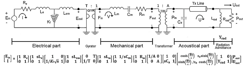
The model consist of three disctint parts coupled sequentially. First, the electrical part comprising the coil, armature, and magnet setup, with the transductance principle of 'moving iron' put into a gyrator. Next, the mechanical part with the strutural mechanics of several parts such as the armature, pin, and membrane lumped into a few components. The conform coupling between the mechanics and the acoustics is taken into account via a transformer. And finally, the acoustics is simply one acoustic compliance taking into account all compressional effects, a time delay, and termination/radiation components.
The Christensen BAR lumped element model
An alternative model has been established that takes into account the issues with the Kim&Allen model. A more logical approach is taken with a one-to-one mapping between physical parts and associated component , and issues with the Kim&Allen are addressed. From the mechnical side the Kim&Allen has too few components to investigate effects related to invidual parts and their behavior, such as the housing moving, changing membrane material, or similar modifications. Also, a single mechanical velocity is assumed, which is not sufficient to include all relevant effects. From the acoustics point of view, the front and rear chambers will not experience the same volume velocity, and so need to be split into different components sitting in different current loops. The time delay in the Kim&Allen only gets a little commenting about the delay observed in the phase, but the physical explanation is missing. If the delay comes from an added tube, it needs to incorporate via lumped components or a transmission line with geometrical properties (radius of tube) included for the coupling to be correct.
Electromagnetics setup
The electromagnetics part of the Kim&Allen model is for now kept as is.
Mechanical setup
The mechanical setup has the most modifications compared to the Kim&Allen model. Now, a differential force is applied, which has a velocity difference associated with it; the velocity difference of course being between the amature and the 'housing' (anything traditionally thought of as non-moving, such as the coils, will be lumped into the housing mass), as the force is no longer pushing off of 'ground' when the housing can move. The armature, the pin, the membrane, and the 'housing' now have invidiual components, so that one can for example see the effect of pin stiffness, the housing moving, and so on. And several velocities must be carried over to the acoustics, as the acoustic compression (and ditto inertia) is no longer a result of a single velocity compared to the Kim&Allen model.
A schematic of the mechanical setup is given below.

The housing can also be connected explicitely to ground via a spring and a damper, but for now the effect of a clamped housing can be included by increasing the mass of the housing. The model will be principally the same, so for now the component count and detail is kept at this level. Each spring has a mechanical resistance alongside it not shown; it is however included in the lumped circuit, only omitting it for the pin.
Acoustical setup
The acoustics setup has also been modfied. First, the rear and front chamber are now included with each their distint component. Also, the compression of each chamber is the result of a differential velocity, as for example the membrane and housing moving in unison cannot compress any air. A tube has been added, alongside a 711 coupler. The coupler can be included as a lumped element circuit of its own, as a transmission line, or as tabular data from measurements or simulations. In the present model, a combination of tabular values extracted from a 711 simulation for the termination impedance and a tranfer impedance approach for evaluating the pressure at the microphone in the 711, was utilized. In this approach, the effect of a tube connecting the receiver and the coupler has been absorbed into the coupler implementation. Any time delay (see above on the Kim&Allen model) will be included with this approach.
The acoustic mass of front and rear chamber could be included also via T-networks, but have been omitted for now, as they are one order magnitude lower than relevant mechanical parts. For microphones, this will not necessarily be true, see the first research item on the list.
The full lumped model now becomes as shown below, assuming translational displacement only, and no modal effects as of now.
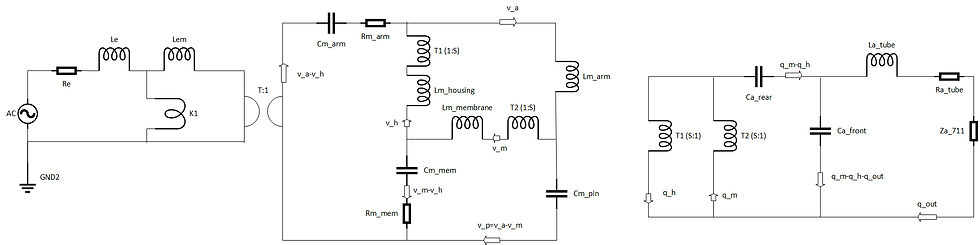
The driving differential velocity for the pressure generation in acoustic chambers takes into account the potential movement of the housing. All individual parts of interest have an associated component. The external force has an associated velocity being the difference between the membrane velocity and the housing velocity. The front and rear chambers see different volume velocities as is the case when the front chamber has an outlet. Two transformers transfer the mechanical velocities from the membrane and the housing, so that the differential acoustic volume velocity is transfered directly to the rear volume, and this volume velocity will be split between the front chamber and the outlet conditions with the tube and the 711 coupler. As already mentioned, the pressure in the 711 coupler is found via a transfer impedance scheme mapping the volume velocity at the input of the coupler to a resulting microphone pressure. Alternatively, one could have lumped components for the full coupler (with tube) added in the above lumped circuit.
Validation
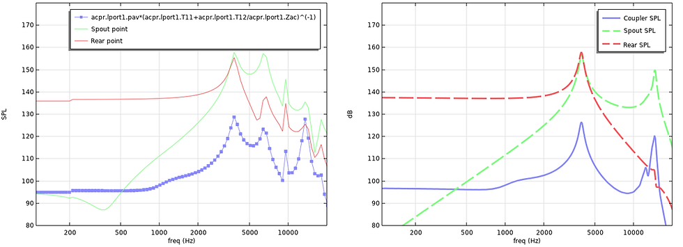
COMSOL Multiphysics recently included a full electro-elasto-acousto finite element model of a generic Balanced Armature model, see https://www.comsol.com/model/balanced-armature-transducer-61741. This model includes all relevant parts with explicit couplings between domains in a finite element method setting. An input voltage can be applied, and the output pressure in a 711 coupler can be evaluted, alongside all relevant variables in the finite element domains. Geometry and material data was extracted for use in the Christensen BAR model, and results were compared. The COMSOL model has a fixed housing as of now, wheras the lumped model results shown below are for a housing mass of 10 times the mass of the armature plus membrane.
Pressure in coupler (FEM vs Lumped):
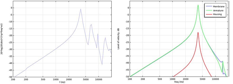
Velocity (FEM top of pin vs Lumped parts):
Electrical impedance (FEM vs Lumped):
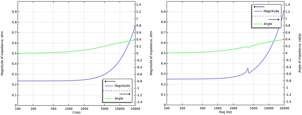
Aside from modal behavior, there is good agreeement between the models without need for substantial fitting, once the geometry and material parameters have been extracted from the finite element model. With the Christensen BAR model one can observe characteristics that are often measured in the hearing aid industry, such a resonances moving depending on the housing is clamped. With a calculation time of 1-2 seconds, different aspects of the construction can quickly be investigated.
Going forward, modal aspects and the torque nature of the setup will be investigated.
Closing remarks on part 1:
If anyone has use for the current model in a company setting, feel free to go ahead and use it, but please let me know if you do. For anyone in academia who wants to use this model or slight derivaties thereof (adding or removing a few components not present in the current figures does not make it a new model), refer to it as the 'Christensen BAR model' or similar, and refer to this blog post and also keep updated on when the paper comes out so a citation can be made. For papers heavily inspired by the above, contact me for co-authorship. Also, this is somewhat of an evolving model, so modal aspects and torque should be included in the next steps.
Comments